Geoprocessing tools
Introduction
The gvSIG geoprocessing extension allows you to apply a series of standard processes to the vector information layers loaded in the layer tree in a gvSIG view (ToC), thus creating new vector information layers which will provide new information for the source layers.
The following geoprocesses have been implemented in the first version of the geoprocessing extension:
- Buffer.
- Clip.
- Dissolve (by adjacents and alphanumerical criteria).
- Merge
- Intersection.
- Join.
- Spatial Join.
- Convex Hull (minimum convex polygon).
- Difference.
The output layer can take one of the output formats supported by gvSIG (it can only be saved in shp format at the moment).
When some geoprocessing tools are applied (for example, Clip) a window appears in which a spatial index can be created for the input layer. This is an internal process which is only carried out once per layer and per new project and speeds up the spatial intersection processes.

To create a spatial index for the input layer which can be used by the geoprocesses, click on “Yes”.
Accessing the geoprocesses
You can run the geoprocesses available in gvSIG with the geoprocessing wizard by clicking on the following tool bar button:

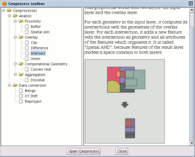
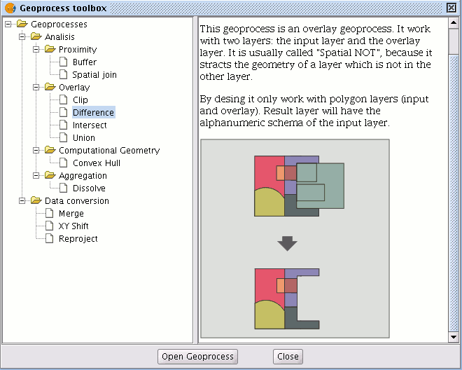
The “Geoprocess toolbox” will appear and you can use it to select the geoprocess you require. To access the different geoprocesses, pull down the tree in the window shown below (double click with the left button of the mouse on the "Geoprocesses" folder and the rest of the folders will appear).

When you have found the geoprocess you wish to use, click on the “Open geoprocess” button.

Intersection
Introduction
This geoprocess operates on two layers, the “input layer” and the “overlay layer”, whose geometries can be polygons, lines or points.
It calculates the intersection with the different geometries in the “overlay layer” for each geometry in the “input layer”, thus creating a new element for each intersection. This element will take all the alphanumerical attributes in the geometries that created it (input and overlay). This is why (it models space areas which comply with the condition of belonging to the two polygons, lines or points that created it) this geoprocess is known as “Spatial AND" operator.
An example of how this geoprocess can be applied:
Given a land use layer (e.g. Corine2000), and a national geological map layer, you can obtain a polygon layer with homogeneous information on land use and geological material.
Running the 'Intersection' geoprocess
After selecting the "Intersection" geoprocess, the following dialogue appears:
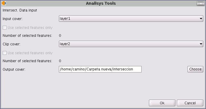
Select the input layer and the overlay layer. You must also specify a file in which to save the results. Finally, click on "Ok" and the geoprocess will be run.
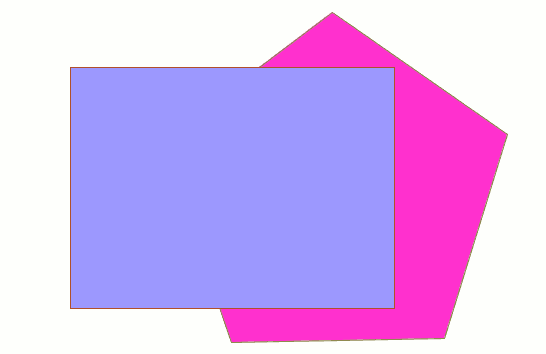
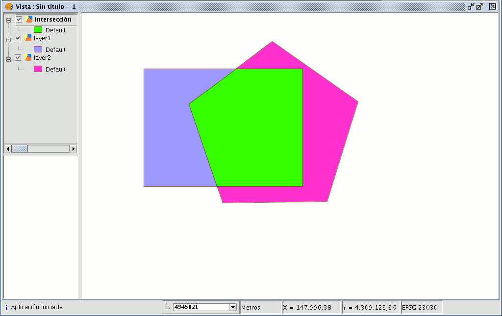
In this case, we will use a very simple example to better understand the function of the geoprocess. The previous figure shows two overlaying polygons. The result of launching the “Intersection” geoprocess with these layers as parameters is as follows:
Difference
The ?Difference?
The “Difference” geoprocess works with two layers, the “input layer” and the “overlay layer”. It is known as “Spatial NOT” and allows you to obtain the areas in a layer which are not present in the other layer. The geometries in both the “input layer” and the “overlay layer" must be polygons, lines or points. The alphanumerical schema of the “input layer” will remain intact in the "result layer", as in the end it gives more information about it.
This geoprocess is very useful in numerous situations. For example, it can be used to complement the "Clip" geoprocess. If “Clip” allows you to exclude everything that does not belong to a geographical area under study, "Difference" allows you to do exactly the opposite; exclude a specific area from our working layer.
A useful example:
Transferring territorial jurisdiction between different governing bodies. Thus, if the national government transfers certain jurisdiction to a regional authority, it can decide to exclude the geographical area of the transfer in question from its data bases.
Running the 'Difference' geoprocess
Running the “Difference” geoprocessClick on the “Open Geoprocess” button to access the dialogue window which allows you to run the "Difference" geoprocess.
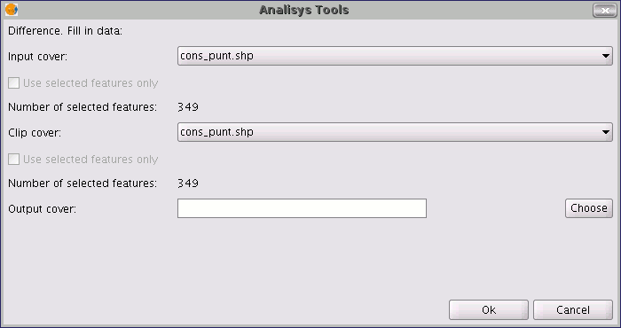
You can enable the “selected features” check boxes at this point of the geoprocess for the input layer and the overlay layer. If you click on the “Ok” button, the geoprocess will be run.
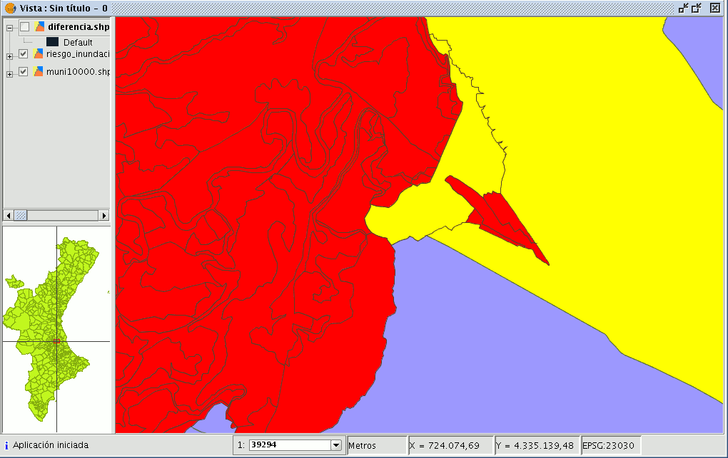
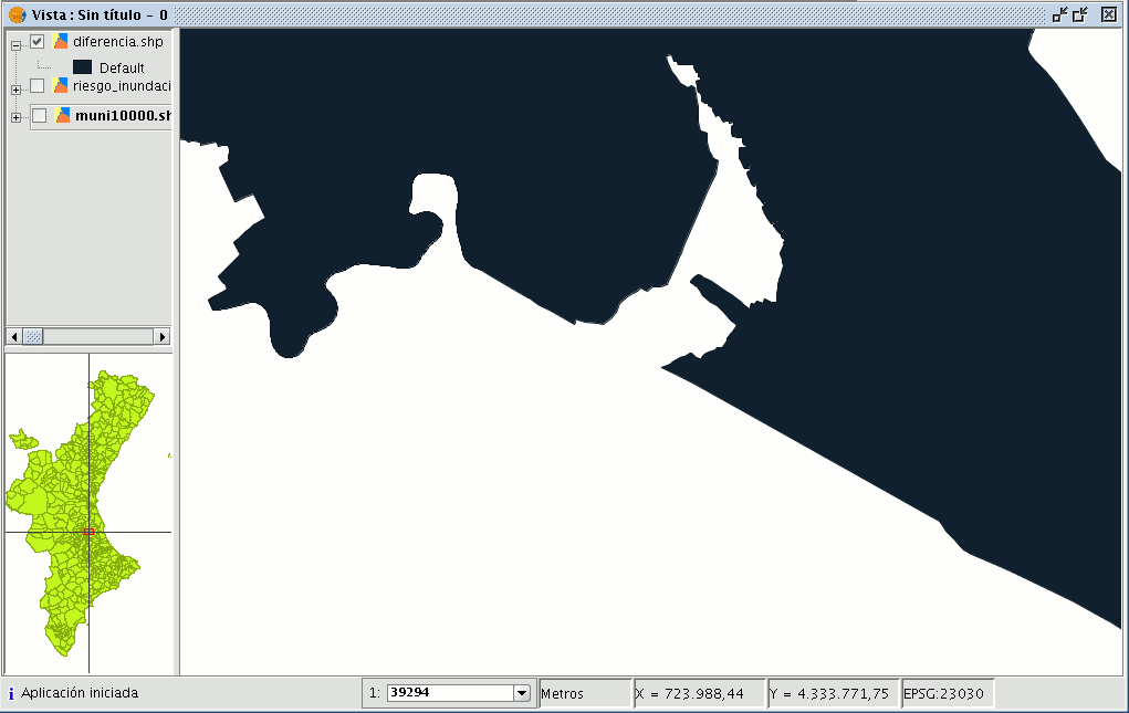
In the following image, the “Difference” geometry appears in black between a flood zone and one of the selected cities or towns. In this case, the new layer resulting from the calculation of the difference will take the schema (alphanumerical attributes) of the geoprocess input layer.
Union
Introduction
This geoprocess is similar to the “Intersection” and "Difference" geoprocesses in that it operates on two polygon, line or point layers to obtain their intersections (this is why these three geoprocesses are known as “overlay geoprocesses”).
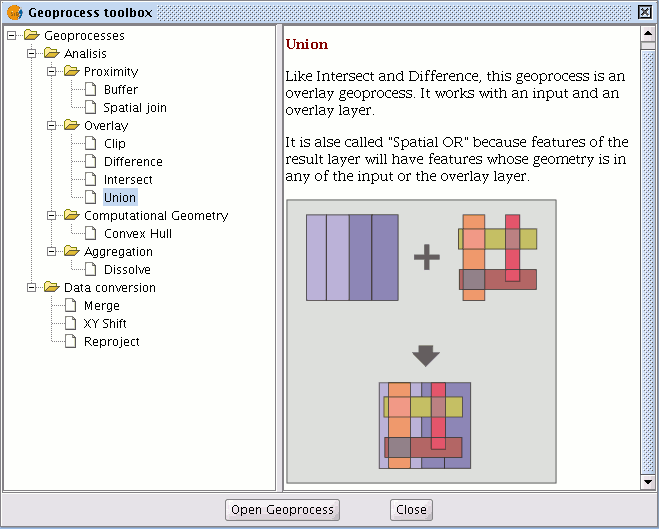
The "Union" geoprocess is known as "Spatial OR", because the result layer is made up of the geometries which appear in the two layers (intersections between the polygons, lines or points), plus the geometries which only appear in one of the two associated layers.
This means that the geoprocess carries out three analyses:
the first time it calculates the intersection of both layers, the second time it calculates differences between the first layer and the second, and the third time it calculates the differences between the second layer and the first.
This geoprocess may be of interest if you wish to generate new layers which show the occurrence of two phenomena so that the occurrence of one of the two or of both is highlighted.
Running the 'Union' geoprocess
If you select the “Union” option, the following dialogue appears:
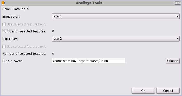
When you have selected the input layer, the clip layer and an output layer, click on "Ok".
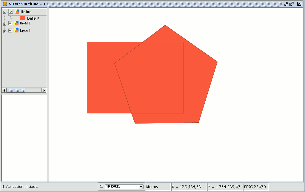
The result layer will have all the intersections and differences between the two layers. If you click on the “Information” button and then on the different polygons in the result layer, you will see that the intersections have all the attributes, whilst the differences only have the attributes of the layer that created them.
